Thursday, October 18, 2012

Oh, Fork Crying Out Loud!

Logic dictates that if one wants to install one's outrageously expensive wheels, first one must have something to install them onto.

This dawned on me slowly and as such, over the recent weekend (between carting tons of no-longer-needed junk out to the footpath for the half-yearly council cleanup and a large selection of other honey-do's), I drained and refilled the oil from the forks. I then used some Mother's brand aluminium polish and a dab of locally produced elbow grease to shine up the fork lowers. Any devoted and regular reader of this blog (ED: does anyone read it, I wonder?) will already recall a previous thread on how I removed the old, dull and chipped black paint from the lowers. Anyhoo, they have come up really nicely with a bit of a polish and I am very happy with the result. They do look heaps better than the black version IMHO.

Then just last night, I went out to the shed, grabbed the top yoke and loosely bolted it on. The left-side fork leg slipped up inside the bottom yoke with just a small amount of persuasion. Not forgetting to first slip on the clip-on, I then pushed the fork up into the top yoke and aligned the top of the stanchion with the top of the yoke and lightly tightened the top bolt to hold it there. Nice!

The other leg proved to be a little more difficult. For some reason it would not fit into the bottom yoke. The hole looked round enough. The bloody thing came out of there just 12 months ago, surely it should go back? Nope. I then checked that there were no extraneous bits of powder coat in there, and even lightly sanded the surface. Still no luck. Add some lube? Nope.

Oh well, there was only one thing left to try; I decided to introduce Ms. Tightass Yoke to my good personal friend, the inimitable Mr. Dremel Grinder. It was a wonderful experience for both and with the smallest amount of tickling, Ms. Yoke yielded to Mr. Grinder and the lightly lubed stanchion slipped neatly into the hole. That put a smile on all our faces. Then it was slip on the clip-on and up into the top yoke it went and then tighten as described previously.


It was a tight, yet strangely satisfying fit!
Now that both fork legs were in and aligned correctly, I torqued up all the bolts and stood back to admire the evening's work. Then it hit me... The forks were on! Yaaaaaaayyyy!!!

Yes, your eyes do not deceive you.
You do see a hammer, a chisel and a jemmy bar!

In other news:

When all round good egg Brett Rosenthal was around a couple weekends ago, he looked aghast at the state of  the original rear inside guard. It was soft, worn and torn. Not a good look. But what to do? Being the skilled artisan that he is, he just happens to produce (at reasonable cost) a selection of replacement parts in fiberglass. And luckily for me, he tells me has a rear inside guard available. I say, "yes please, I will take one".

When I attended the monthly meeting of the Moto Guzzi Owners Assoc of NSW on the following Tuesday, he had it in his bag. Very nice it is, too. The following night I drilled it, pop-riveted the compliance plate on, and fitted it to the frame. I am very happy with the result.


This is what 32 years of faithful
service looks like


All bolted on and ready for the next 32 years

Coming up:


New switches are on their way and will arrive soon. Also may try to fit braking system.

Stay 'tuned'...

Monday, October 8, 2012

The wheels on the Guz go round and round...I hope

One of my non-negotiable's for this project has been to replace the bike's original snowflake pattern mags with spoked wheels. Being an old fart from a bygone era, I have always liked the look. So my first task when thinking about a re-design was to pick up a set in reasonable nick. There is pretty much only one choice for wire wheel conversions and that is to find a set of Borrani wheels from a 3 disc brake bike such as a T3 or similar. After lots of looking around, I eventually grabbed a pair of wheels from two different T3s via two separate eBay purchases. What I did not consider was how bloody expensive they can be!

The front came with bearing carriers, but no rotors. The rotor carriers from my LMII wheel are too wide due to the narrowness if the mag wheel hub vs the greater width of the Borrani hub. What is needed therefore to adapt my semi-floating discs, is to fit them up to the narrower carriers from a Convert. These, too, were tracked down at further expense.

The rear wheel came with its own set of problems. There was no bearing carrier, but luckily I was able to get one for postage from one of a great bunch of blokes on the US-based Guzzitech forum. The rear rotor from my MKII mag then just bolts straight up to that.

Finally, a whole raft of sundry bits were tracked down second-hand via eBay or purchased new, including both axles, spacers, nuts, washers and bearings. Finally all parts were in my greedy hands and everything salted away for when I finally got around to assembly... or so I figured.

One thing that bugged me was that while the wheels were in good shape, they were showing their age. I attempted a refresh myself, but I learned very quickly that I don't have the patience for this tedious job.What I do have, however, is a credit card! So I packed then both up and shipped them off to Ash's Spoked Wheelz in Brisbane. When they came back, they looked brand new and unused, unlike my credit card which took the hammering of its life! Please do not ask me how much they cost, as I have erased the figure from my memory to protect my own sanity.

The wheels after full clean, polish, reassemble and true

The carriers from the Convert were also tired looking, so I cleaned them up and gave them a fresh coat of paint.

Masked and undercoated

Painted. That bottle was full when I started this job!
After awaiting a suitable time for the paint to dry/cure, I successfully bolted up all parts to make the complete front wheel, remembering to install the 76mm bearing spacer! All that was needed do then was find out the correct Le Mans II disc to disc width and compare. I was too stupid to take that measurement before pulling down the original wheel, but a simple call out to AIGOR and the answer came in at 145.5mm. A quick check of the newly built wheel and I had an exact match. This wheel building business is too easy!

Famous last words...

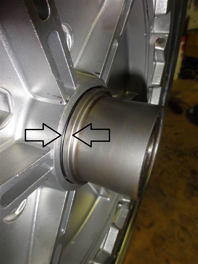
That is when the rear wheel hove into view and I took the same cavalier approach until the point where I installed the bearing spacer and it fell over inside the hub. It wasn't even making contact with the cups that hold the wheel bearings! WTF? Was it too short? Nope, it came in at 74mm which is the correct length. Time to take another look. Then it came to me. The center of the hub looked like it had shifted outwards, effectively increasing the distance between the wheel bearings. Could that be it? Hell, I had NEVER even seen the inside of one of these wheels before. How would I know?

This looks suspicious. Should the points indicated by
these two arrows be meeting?

The other side
Even  though I thought this was the obvious reason, I timidly put it out onto the interwebs and forums for some advice. However I received very little feedback. Some of those sites seem more interested in guns, religion, politics, dogs... anything but Guzzi's!
Maybe I am not the only one to never look inside a Borrani rear wheel, haha!

Anyhoo, I should have learned by now to go straight to the reliable source; AIGOR. In no time I had received valuable advice from Rod Yeomans, Doug Foskey, Mark Glanfield and Brett Rosenthal. The wheel hub had definitely shifted and needed pressing back in. Then, on the brake side there is supposed to be a 55mm circlip (obviously missing, haha!). The purpose of the circlip is now obvious.

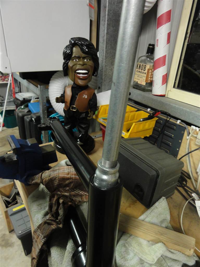
So off I go down to the local hardware store and I picks me up some lovely 5/8th threaded rod and a handful of bloody big washers and nuts. Next, add a few bits and pieces found lying around in the shed and I haves me a make-shift press to do the job! Hyuk hyuk!

Spacers, lock-nuts, multigrips on brake side

The business side

Wind that bastard in!

OMG, it's working!

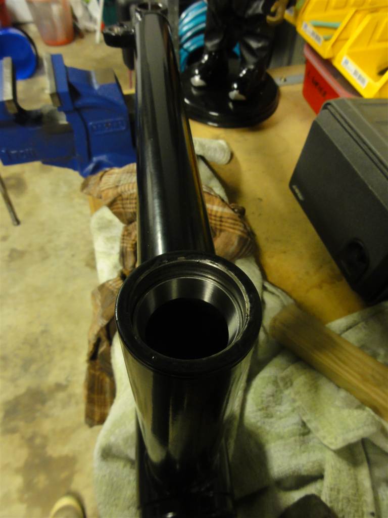
Now in correct position

The brake side, now showing the channel for the circlip

It sure is nice when something goes to plan. I was still short one circlip, but later the same day Brett Rosenthal came over for a squiz and what should he have in his box of goodies? Not one, but three circlips of the size and type needed for the job. Whatta guy! Thanks Brett, you saved me again. A quick check showed that the bearing spacer was a nice fit against the inner races of the two wheel bearings...relief!


I can see a spacer! I can see a spacer!

Once that was installed I then proceeded to reassemble and fit the various bits that make up the cush drive. Prior to this install, I had drilled some holes through the rubber pieces. This is a widely recommended method for softening the cush drive up a bit to make things easier on the bike's drive components. I have seen recommendations to completely remove every second pair as well, but decided not to take that step.

One important step though, is to ensure all parts are nicely greased. This way, no parts will rust and bind the cush drive, negating its purpose and causing other drive components to wear abnormally or even fail completely. You must use rubber grease inside the drive as normal grease is likely to cause the rubber components to fail. Also, do not forget to install the O-ring on the shaft.

1. Cush rubbers drilled
2. Rubbers and cush drive plate greased with rubber grease
3. O-Ring installed on shaft
4. Shaft greased with bearing grease


1. Cush drive plate installed
2. Snap ring installed
3. Locking tab installed

One thing that I have been told by numerous sources when mentioning the rear Borrani wheel is, "do not forget to install the 'top hat' spacer against the bearing on the brake side". Well, since I am yet to fit the wheel to the frame, I cannot do that yet, but I promise not to forget! Just for the record, so you all know what I am talking about, here are a couple pics of the spacer and how it should fit. Note how the smaller end of the spacer fits against the inner race of the bearing.

Spacer, circlip and bearing

Spacer in position

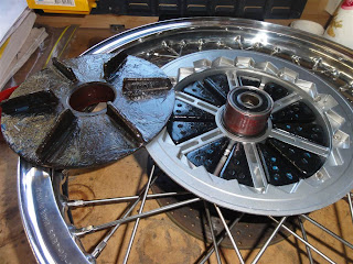
So, finally after all the drama all is good in the world and I now have two wheels ready for rubber and eventual fitting to the bike when the time is right.


Check out these beauties!

Coming up next:

Not sure, haha! I think it could be overhaul, polish and fit front forks. I can then think about getting the brakes and wheels back on.

Stay 'tuned'...

Tuesday, October 2, 2012

Swingarm, bevel box and rear suspension

OK, so moving right along. I am now working on installation of the swingarm, bevel box and rear suspension.

The first job is to remove the old carrier bearing from the swingarm. I had been putting this job off, simply because I had no clue as to how I was going to get it out. Looking down inside the swingarm from the bevel box end, there is very little 'lip' visible of the inner race of the bearing. This makes it hard (for me, anyway) to get enough purchase for a drift or punch to be able to work.

In the end I realised that if I could get something down the tubing that just fit with a millimeter clearance, it would still be too large to fall through the center of the bearing. All I would need to do then was whack it out with a drift. I fished around and found that a 22mm socket would do the job after I removed some of the redundant weld at the bevel box end.

So here goes...

Remove circlip with long-nosed circlip pliers

Grind off any rough weld

Heat swingarm with hairdrier to "bloody hot"

Drop the 22mm socket down the tube

Place improvised drift down the tube and give an almighty
whack! with a BFH


...and out she drops!


Empty!

Here is the culprit
The old cardan joint slips quite easily into the bearing and as you can see it would have been spinning inside the bearing rather than the bearing spinning with it. The old cardan joint also had a small amount of play in one end. It seems like this setup was due for replacement ASAP.  I am not sure of the history of the bike, so have no idea how many km/miles this setup had on it, but whatever it is, it was too many, haha!

Here are the old and new cardan joints. Out with the old and in with the new:


So that is it for the night. Not bad for less than an hour's work. I should not have spent so much time worrying about it!

3/10/12  UPDATE:

Tonight the new carrier bearing is in, and also the two swingarm bearing races:

Pre-frozen carrier bearing driven in, followed by the circlip

Apply heat

Apply force

Apply even more force!

Swingarm bearing race is home


7/10/12  UPDATE:

All available time this weekend was spent on completing the installation of the rear end of the bike.

I hunted around and sourced some 3% Moly grease for all the splines in the drive line and also some Loctite bearing retainer fluid to assist in the mating/fixing of the cardan joint into the carrier bearing. The cardan/U-Joint had spent a chilly night in the freezer prior to installation.


Grease splines

Apply bearing retainer

Temporary poly pipe guide to hold
joint in aligned position

Drop guide over U-Joint

Bash the shit out of it

Voila! Its in!
(don't forget to remove piece of poly pipe, Brad)
That wasn't too difficult after all. Thanks to all those who offered help via the AIGOR mailing list and also to Brett Rosenthal here in Sydney and Rodney Yeomans from up on the Sunshine Coast.

Ok, next, install swingarm. But before I do, time to torque up the frame and center stand bolts.

I'm scared!
I packed and installed the swingarm bearings, along with their spacers and seals and readied myself to this 'difficult' task.

Sometimes you can think too hard about things and how you are going to get them done. Sure, you gotta do your research so that you don't stuff up, but after that, it's best to get stuck in. I worried about the fitting up of the swingarm and the U-Joint to the transmission, getting the rubber boot on and aligning the swingarm. In fact I spent too much time on the inter-webs when I should have just gone out to  the shed and done the job.

The truth is, it was a piece of piss and took all of 10 minutes to get the arm on, the adjuster nuts loosely in, and the rubber boot fixed tight. The trick to the rubber boot is to fix it nice and tight to the transmission end, then roll it back on itself out of the way to allow for the easy alignment of the U-Joint to the transmission splines. Once that is done and the adjuster nuts go in, then just unroll the boot back over the swingarm and tighten the clamp.

Swingarm on
Once I got to this point, it was important to centrally align the swingarm using the adjuster nuts and a digital vernier caliper's depth probe to ensure that each adjuster (once snugged up to their bearings/not too tight/no side-to-side movement) sticks out the same distance from the frame. This should be done prior to fitting any suspension or the bevel box. It takes a bit of fiddling around to get both the tension and alignment done, but patience is the key here as it ain't rocket science baby!

After I was  happy with that, it was time to fit the lock nuts and tighten to spec. These nuts have a hole that allows the allen key to be fitted to the adjuster to stop any accidental tightening. The tip here also is to grease the adjuster's threads, and also to fill in the hole with grease. This will keep the whole assembly water free and  happy as there is no further access to these bearings etc.

Adjusting swingarm bearings and alignment
Tighten lock nuts while holding adjuster screw
in desired position
Next in line was to fit the Ikon shock on the brake side, remembering to smear some grease on the frame shafts first. The top nut will need to be removed later to add the hand-grip. However as the other end of the grip fastens to the brake proportioning valve that is not yet fitted, I have left it off for the time being.

One shock on
Then, it's around to the other side to insert the greased drive shaft to the U-Joint, add coupler and slide-fit the bevel box. Tighten up the four acorn nuts to fix it to the swingarm. NOTE: Brad, do not forget to include the O-ring between bevel box and swingarm.

Finally, fit the shock absorber, and we are all done!

Bevel box and shock absorber on

Another view

From the top
Luckily for me, all-round great bloke Brett Rosenthal paid me a visit (see next blog on the rear wheel), and pointed out that I had omitted to fit the battery strap and battery earth cables when I installed the battery tray. Thanks Brett, you saved me a shitload of trouble down the track!

Battery strap and earth cable installed
just in time!
And so here we end the saga of the rear end. Hopefully, all has been done correctly and the new U-Joint and bearing will go on to give many years of faithful service.

Coming up next, WHEELS !

Stay 'tuned'...